Projects
-
Accelerometer Weight Scale
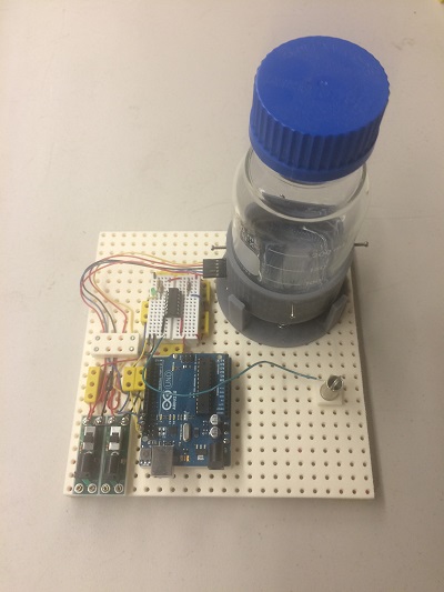
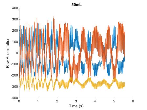
The weight scale accelerometer is designed to weigh a bottle by identifying the change in accelerometer patterns at different volumes of fluids. Here, we have a bottle to fill with different volumes of water mounted on a spring platform to isolate it from the table. We have a high speed small vibrator and an accelerometer measuring acceleration in the X, Y, and Z direction. As we place different volumes or weights of fluid, we get different complex acceleration patterns over time. Even for the same setup, these acceleration patterns differ sometimes by a little or sometimes by a lot. We are developing automated software to read and analyze these patterns. The relatively simple setup offers us the ability to collect lots of data. This is precisely what is needed for developing predictive software. The first part of the data analysis was to do Fourier transform of the raw data. We can then start determining statistics on these graphs such as minimum, maximum, mean, median, and standard deviation. We look at frequency peaks and amplitude for further information. We hope the methodology of determining weight through the study of patterns and their characteristics across a large data set will offer insights into disease prediction through monitoring of a range of diverse biomarkers over time.
-
Auto Code Generator
Auto code generation is the result of an accumulation of work by Adam Veres, Chip Pearson, and Doug Hill. Adam worked on the Python or Computer side, Chip on the AVR microcontroller side, and Doug on developing the integration of the two with auto code generation. The result is an incredibly powerful piece of software. This software allows for the initial control software construction of a system with the simple selection of the devices that are in it, along with any specific device specification such as device pins. The MEC mechanical system allows for the easy construction of complex instruments such as the bioreactor. But without an equivalently powerful software system, the control and operation of these system would be severely limited. What made this software system possible was the serial I2C device bus structure that Doug envisioned. Here, devices like an LED or button are assigned to microcontroller and given device IDs. Devices are developed with a standard set of commands. The menus that are needed for control of these devices are auto generated from script. To sum this all up, complex systems can be constructed with the required core of software having the ability to be auto generated and test each of its components.
-
Bioreactor
The analytical bioreactor can be used for applications ranging from producing biofuels to curing diseases. One application envisioned is a personalized bioreactor to train a patients T-cells to attack cancer. Control of the cellular environment is needed for this type of application. Our Analytical bioreactor is created in a loop and developed with thermal and media flow control in that loop. The bioreactor has the ability to inject air or gases such as CO2 into the media. It also has a media and waste disposal system. The device houses a serial dispensing system with precise control over injection volumes of various biomaterials, small molecules, or nutrients as needed. Cell density can be maintained and controlled through an optical density sensor. An onboard minicomputer with a display and keypad takes care of basic operations. Another application would be in a class environment enabling high school or college students to grow cells and be motivated with the challenges of engineering real world solutions.
-
Coulter Counter
A traditional Coulter counter is a device to count or size particles suspended in electrolytes. These particles include cells, bacteria, prokaryotes, among other micro organisms. General application today include blood counts, malaria and sickle cell anemia diagnosis, and particle detection. Although popular in hospital settings, the device is severely limited in versatility and accessibility in financially limited settings such as rural areas where they might need. This project was made with a mindset to reduce costs as well as to integrate the Coulter into a larger system. The system, set to function with limited resources and little intervention, has the capability to grow and circulate cells, perform optical density, and with the Coulter-perform size analysis. The comprehensive system provides a practical solution to the inaccessibility of diagnostic devices. As of now, the system is capable of detecting a range of aperture sizes and slight perturbations in the system like air bubbles. Further studies must be done to help understand the potential effects on the measurements.
-
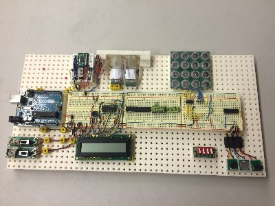
I2C Test Board
The I2C test board was the origin of all of our early I2C devices. The I2C serial bus and device structure was a pyridine shift over the previously used parallel structure in our lab. Daughter cards with latches were placed on top of Arduino boards. The Arduino takes a less prominent role in this serial I2C system. It acts as a translator between serial USB connections from computer to the serial I2C of the system. Our I2C bus requires four wires: 5volt power, Gnd, SDA (Serial Data), and SCL (Serial Clock). We added one additional wire for 9 Volts power if needed. The wire was used for powering solenoids, motors, and any other device that required additional power. This shift offered essential changes in hardware to be equally important if not more important than software. Effectively, it allowed for standardization and simplification of evolving new systems. This simplification on the software side was so straight forward that it allowed for auto code generation. Our system operates by the computer (often being directed by the user from a menu) sending a command set to the Arduino. Then, the Arduino translates this to the I2C bus. The command set starts with an AVR microcontroller address being sent down the serial bus with the selected AVR acknowledging in turn. The device ID gets sent down the I2C serial bus along with a command. The command could be as simple as turning on an LED to reading a button. Looking at the I2C test board, you can see some of our first I2C devices which included: LED, button, potentiometer, LCD display, 4X4 keypad, and Solenoid. Many of these devices where originally tested with the parallel structure.
-
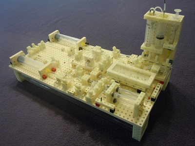
MEC Instrument
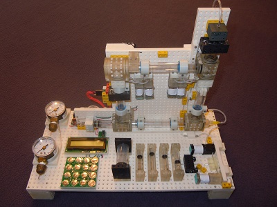
This was the first MEC multi-scale fluidic instrument demonstrating the scope of the MEC system. It showcases the integrated microfluidic device and socket. The instrument draws from our large assortment of macro-components. These components include: storage, pumps, valves, fluidic joints, and air tanks. Assembly took place on a mechanical baseboard platform. The devices are interconnected with 3/32 inch Tygon tubing in a breadboard fashion. One of the key fabrication transitions that allowed us to take a jump in both complexity and reliability was the use of 3D printing. 3D printing was used in most of the components shown. This system also includes a microfluidic device fabricated with PDMS casting method. The device is then packaged in a 3D printed shell, and plugs into a MEC fluidic socket.
-
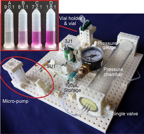
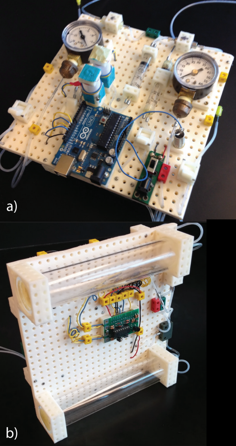
Unit Mixing System
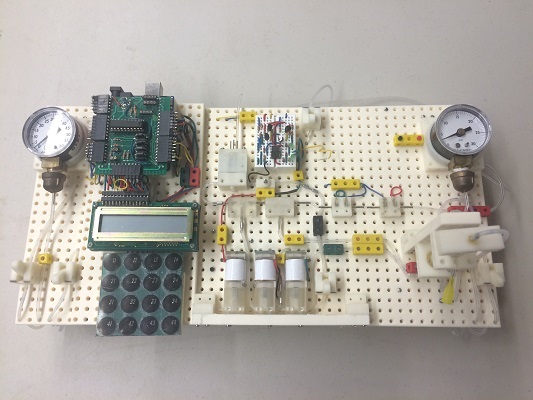
This system demonstrated a simple mixing operation by performing an acid-base titration. An acid-base titration remains a classic chemistry lab experiment used to measure the equilibrium constant of a weak acid or base. The MEC-based titration instrument delivers unit volumes of either water, sodium hydroxide solution or phenolphthalein solution to a vial. The titration instrument also features an integrated pressure chamber that makes the instrument portable. This would make it well suited for use in a classroom. To fill Vial 1, the titration instrument combined nine unit volumes of water, zero unit volumes of sodium hydroxide solution, and one unit volume of phenolphthalein solution (a mixing ratio of 9:0:1; final NaOH mass concentration = 0). Vial 2 received unit volumes in a ratio of 8:1:1. Vial 3 received a ratio of 7:2:1, and Vial 4 received a ratio of 1:8:1. Each vial received a single unit volume of phenolphthalein solution (a pH indicator that turns from clear to pink at pH > 8.2). The observed colors of the solutions ranging from clear in Vial 1 to pink in Vial 4 confirm the increasing pH from Vial 1 to Vial 4 and the successful operation of the MEC-based titration instrument.
-
Compressor
The compressor was the first instrument in the TEC center to integrate electronics with fluidics. We selected it to solve the problem of very short operation times that pressure and vacuum chambers provided. This device provided a continuous source of vacuum and pressure for our fluidic energy source. The system is controlled from a laptop through the USB port connected to the Arduino. The Arduino has a Daughter card designed to plug into a Arduino with additional support circuitry. In this case, the daughter card had two FETs, which could drive the DC motor. The motor drives a wheel, that in turn drives a slider, with the slider driving a piston. The last critical part of this system are the one way valves, allowing the piston to either pull air to form a vacuum or press air to build up pressure. This system further demonstrates our mechanical valves. The compressor was able to reach pressures of close to 20 PSI and could achieve a sufficient vacuum level to support our pumps.
-
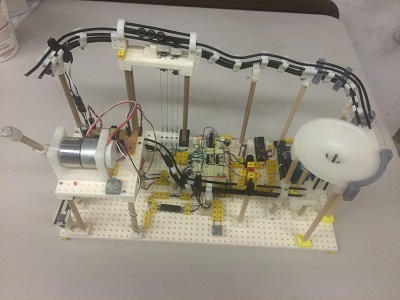
Marble Machine
This is one of many marble machines under development, each with its own unique method of marble transportation. This is the product of a new program for the TEC Center called Outreach. Outreach is designed to teach a large number of students engineering skills and principles, preparing the students for rigorous real world challenges that the TEC center faces. There are several basic components that a marble machine must have. First, we must be able to lift a marble from a lower rail to an upper rail. This was accomplished here with a motor and a magnet on the end of a single spoke. As the motor turns the spoke with a magnet on the end, the metal marble is lifted between rails. Next, we wanted a way to release the marbles in a timed fashion. Here we used a dual gate system actuated with muscle wire. As current is run through muscle wire, the wire heats and contracts. The contraction pulls a pin down, releasing a single marble to a lower gate. The pin then goes back up, holding back any additional marbles from following. The process repeats for the next gate pin, and a single marble is released down. The marble rolls around a turn into a funnel to the lower rail, where it is picked up and raised back to the upper rail, before the process is repeated. Along the way, there two photo detectors tracking marbles movement. Two embedded microcontrollers feed information back to the laptop. The system was well suited for advancing the MEC system and accompanying software.
-
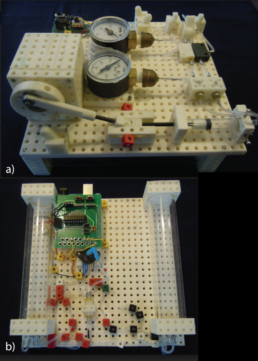
Pump
The pump is designed to be controlled by a laptop through an Arduino interface. It has two on-board chambers for pressure and vacuum. Each chamber has manual and electrical monitoring of pressure and vacuum levels. They both have electrically controlled external feeds, so that outside lab air pressure and vacuum can be used to maintain chambers. Pressure and vacuum are electrically controlled sources to the pump piston, drawing fluid in and out of the pump chamber. The flow direction is set by the one way valves. The pumps use a modified syringe chamber with a plunger. The pump uses electrically controlled solenoids to source the pressure and vacuum to the pump piston. The pump uses one way valves in order for fluid to be transferred in a singular direction. The pump system contains one electrically controlled pump and one mechanically controlled pump.
Thanks to the supporters of the TEC Center!
-

The Center for Bioengineering Research at the University of California, Riverside
Development of the MEC system was supported by Prof. Jerome Schultz and the Center for Bioengineering Research at the University of California, Riverside.
-

The National Science Foundation
Development of the MEC system was supported by the Instrument Development for Biological Research (IDBR) program of the National Science Foundation under award DBI-1353974.
-
Sophomore STEM Success Awards from the Office of Undergraduate Education at the University of California, Riverside
Three of our students— undergrads Raymond Iu (Bioengineering), Hayden Karich (Mechanical Engineering), and Manoel Tamraz (Bioengineering)—received the Sophomore STEM Success Award from the Office of Undergraduate Education at the University of California, Riverside.
-

Best Buy Foundation
Thank you to the Best Buy Foundation for supporting the TEC Center!